Mesh2Solid Pro
The free version recognises planes, cylinders, cones, tori, spheres, threads and freeform and exports STEP. Pro gives you the tools to rework the result, check it and export exactly what you need – all in your browser, your files never leave your computer unless you open them in Fusion.
Pro is required for any commercial use. To enter your key, click “Free / Non Commercial” at the top left of the app. Licence terms
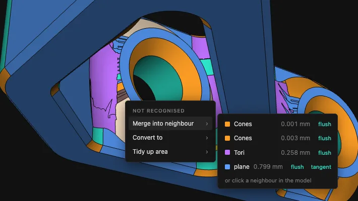
FacesConvert a face or merge it into its neighbour
Sometimes a fillet falls apart into several pieces, or a narrow strip stays red (“not recognised”). One click makes such a piece part of the neighbouring face – or you turn it into a plane, cylinder, cone or freeform face on purpose.
Each neighbour shows how far the mesh deviates from it. “flush” only straightens the shared border, “tangent” lets a face run smoothly into a plane.
How: click a face → “Merge into neighbour” or “Convert to”. Hover a neighbour and it lights up in the model. Every change can be taken back with “Undo”.
FacesTidy up area
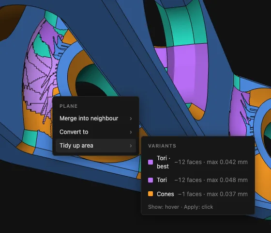
Where the mesh is coarse, you get a patchwork of small cylinders, cones and tori. “Tidy up area” looks around the face you click for the shape that describes the area best as a whole and replaces the patches with a single face.
You get several variants, each with the number of faces saved and the largest deviation. The best one is preselected; hover a variant to preview it in the model.
How: click a face → “Tidy up area” → pick a variant.
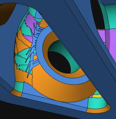 before
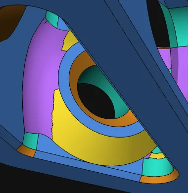 after
afterA few clicks turn the zigzag into one torus and one sphere face
FacesExtend
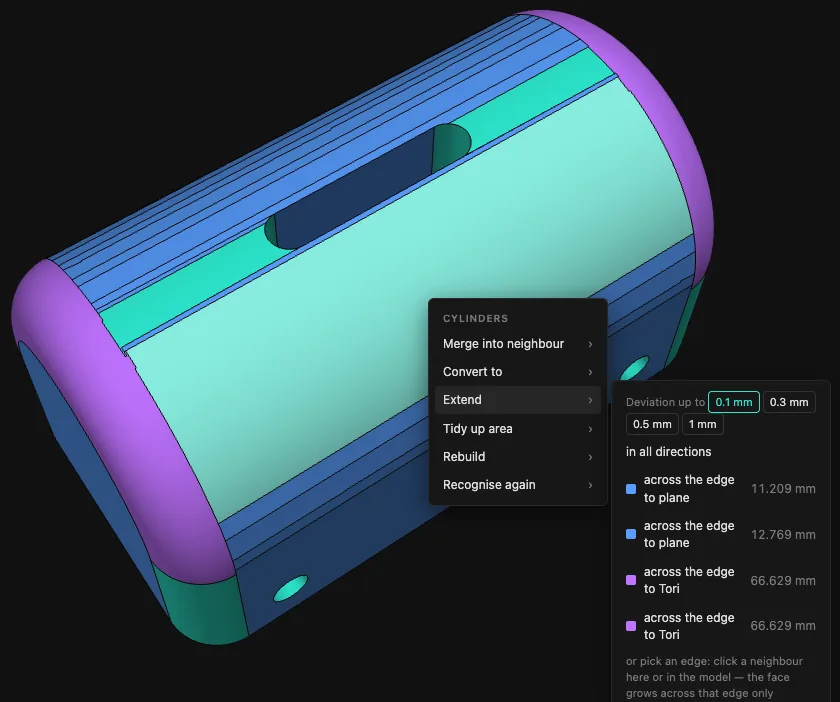
A round is recognised, but dozens of narrow strips hang along its edge, each taken for a plane of its own. “Extend” lets the clicked face grow over its neighbours: every strip that lies on it within the deviation you choose becomes part of it.
You pick the allowed deviation from 0.1 to 1 mm and whether the face grows in all directions or only across one particular edge.
How: click a face → “Extend” → pick the deviation → “in all directions” or one edge.
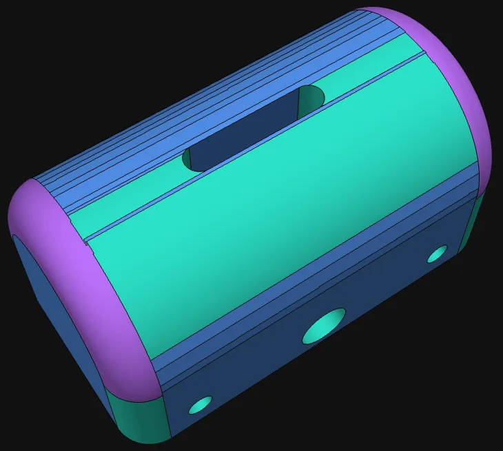 before
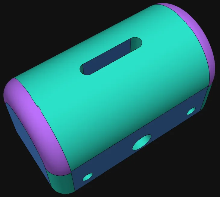 after
after35 strips taken in one step: the lid is one cylinder
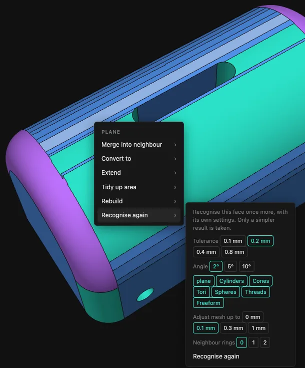
FacesRecognise again
Sometimes the automatic recognition gets one spot wrong: a chamfer turns into a cylinder, a round falls apart into planes. “Recognise again” runs the recognition once more on just this face, with your own settings.
You pick tolerance and angle, which kinds of shape are allowed, how far the mesh may be adjusted to fit the shape, and whether the rings of neighbours come along. The result is only taken if it is simpler than before and makes no invalid faces.
How: click a face → “Recognise again” → pick the settings → “Recognise again”.
FacesEdit mesh: cut along edges
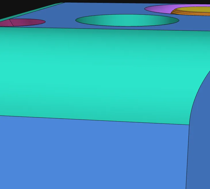
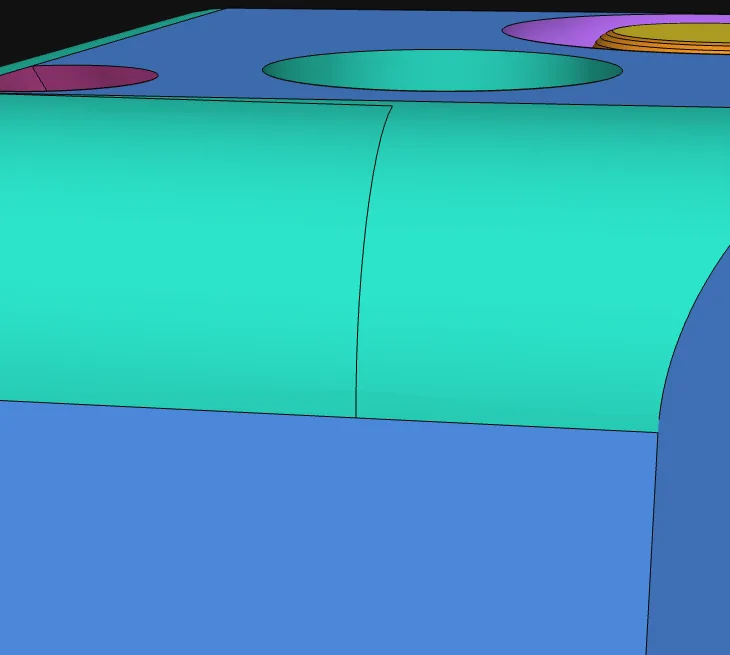
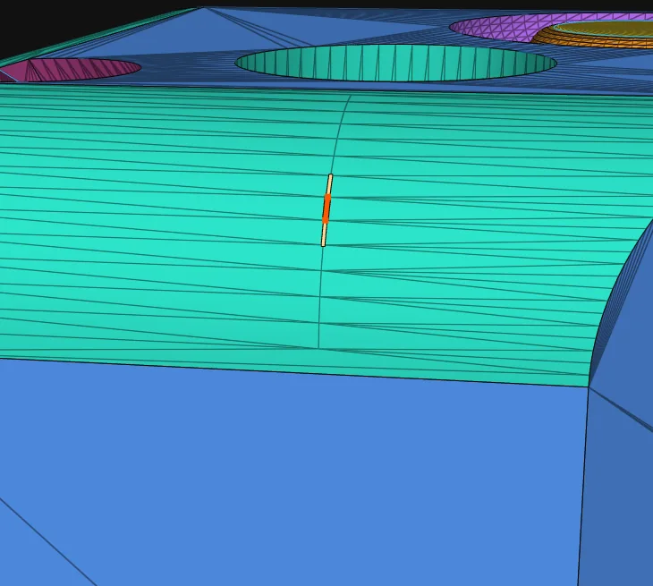
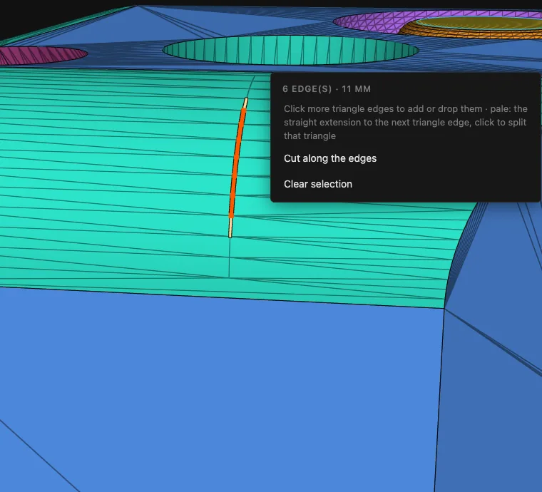
Sometimes you see an edge in the mesh that the analysis missed, or a face drags a stray bit along: a few triangles that belong to its neighbour. In “Edit mesh” you pick single triangle edges and cut the faces exactly there.
Each picked line shows a straight extension at its open ends, through the next triangle to its opposite edge. Click it to split that triangle and take the piece; the next extension appears at the new end. So you trace an edge cleanly, triangle by triangle, even where the mesh has no triangle edge. When you cut, each part gets the simplest shape that carries it.
How: view “Faces” → “Edit mesh” → click a triangle edge → click the extensions step by step → “Cut along the edges”.
 before
 after
afterThe seam traced step by step and cut: the fillet is split at the seam
HolesSet a hole to a thread size
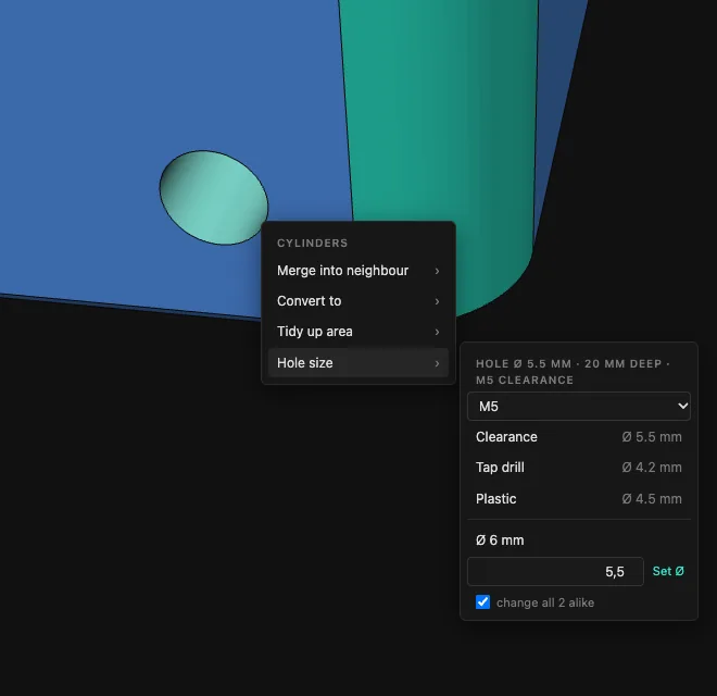
A hole in a 3D-printing model should take an M5 screw? Pick the thread size M2 to M16 and the purpose – clearance (the screw passes freely), tap drill (for cutting a thread) or plastic (screw straight into the print) – and the hole gets the matching diameter.
Mesh2Solid shows the hole’s diameter and depth and tells you which thread size it already fits. Change all identical holes at once if you like; a free diameter works as well.
Or a real thread right away: “Cut thread M5 × 0.8” sets the hole to the minor diameter and cuts an ISO right-hand thread into it – in the STEP as thread flanks made of helical faces, not just a plain cylinder.
How: click the wall of a hole → “Hole size”.
CheckDeviation mesh → STEP
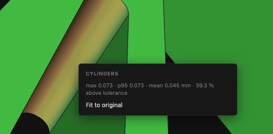
How accurate is the result? The deviation view colours the model by the distance of every mesh corner to the finished STEP face: green fits, yellow is at the tolerance, red above it. Below you see the maximum, the 95th percentile, the mean and the share above the tolerance.
Click a face to get the same figures for it alone. If a cylinder, cone or plane deviates too much, “Fit to original” refits it to the original mesh.
How: Pro tools → “Deviation”, then click a face.
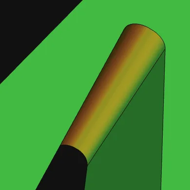 before
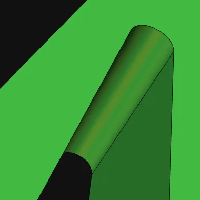 after
afterCylinder fitted to the original: largest deviation 0.073 → 0.018 mm
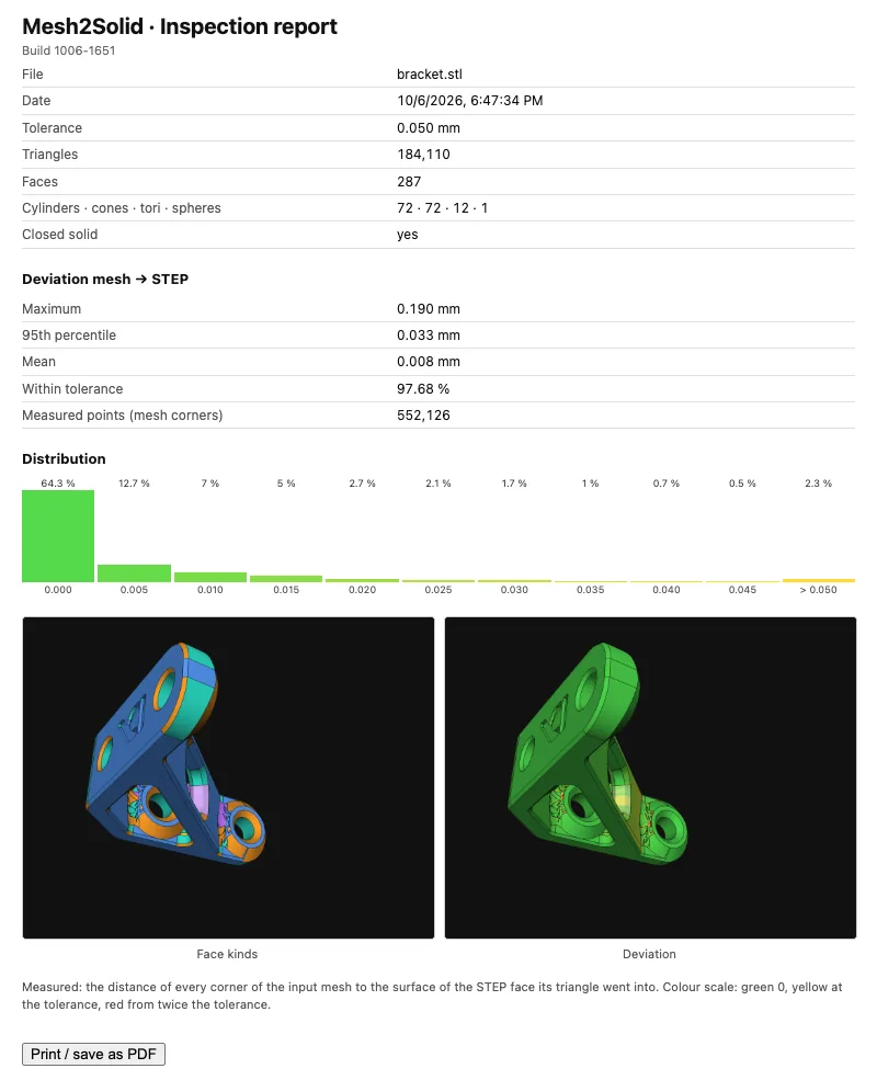
CheckInspection report as PDF
For customers, colleagues or your own records: the inspection report puts the file, tolerance, number of faces, the deviation as figures and as a distribution, and pictures of the face kinds and the deviation on one page.
It opens in a new window; print it from there or save it as a PDF.
How: Pro tools → “Inspection report”.
CheckCheck STEP validity up front
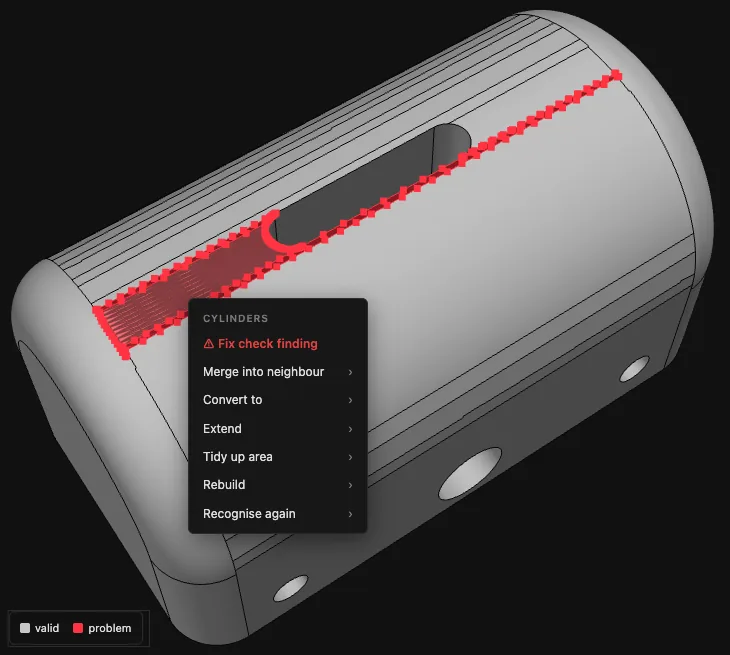
Not every face that looks fine is accepted by a CAD program: a border that touches itself or a thin spike is enough for the import to report the face as faulty. The “STEP Validity” view estimates this right in the browser and colours suspect faces red.
Click a red face and the menu starts with “Fix check finding”. Mesh2Solid then looks for a repair – cut off the spike, join short edges, merge the face into a neighbour – and keeps it only if fewer faces are suspect afterwards.
How: Pro tools → view “STEP Validity”, then click a red face → “Fix check finding”.
RepairClose gaps in the mesh
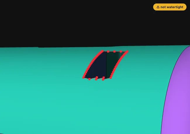
A mesh with holes does not make a closed solid. Mesh2Solid marks open edges red in the model and reports the number of gaps. One click closes them. On curved faces too – cylinders, cones, spheres – the patch follows the curvature, so the same face is recognised afterwards.
How: open the mesh → Pro tools → “Close mesh gaps” (only shown for open meshes).
 before
 after
afterA hole in the curved lid: one cylinder again after closing, without a seam
RepairFind and fill cavities
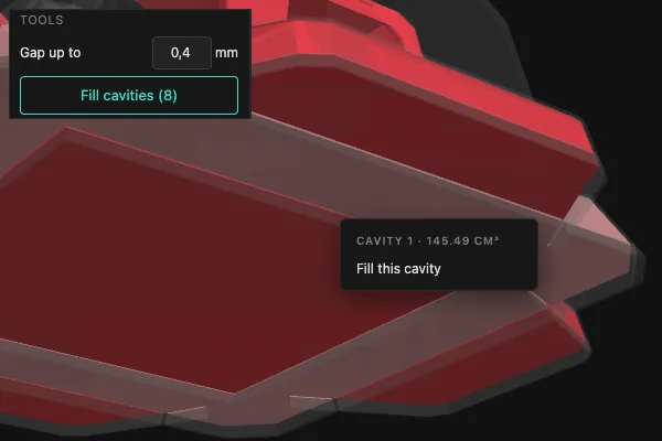
Models put together from several parts often hold enclosed cavities: spaces you can't see from outside that still end up in the STEP as an inner shell of their own. Such unwanted cavities sometimes even make the STEP invalid – filling removes them. The “Cavities” view makes the model see-through and shows every cavity in red, with its volume.
One click fills a single cavity, “Fill cavities” fills them all – you get one solid body. Spaces that are open to the outside only through a hairline gap, for example parts exported slightly apart, count as cavities too, up to the gap width you set.
How: Pro tools → view “Cavities” → click a cavity or “Fill cavities”.
ExportPick, rename and export single bodies
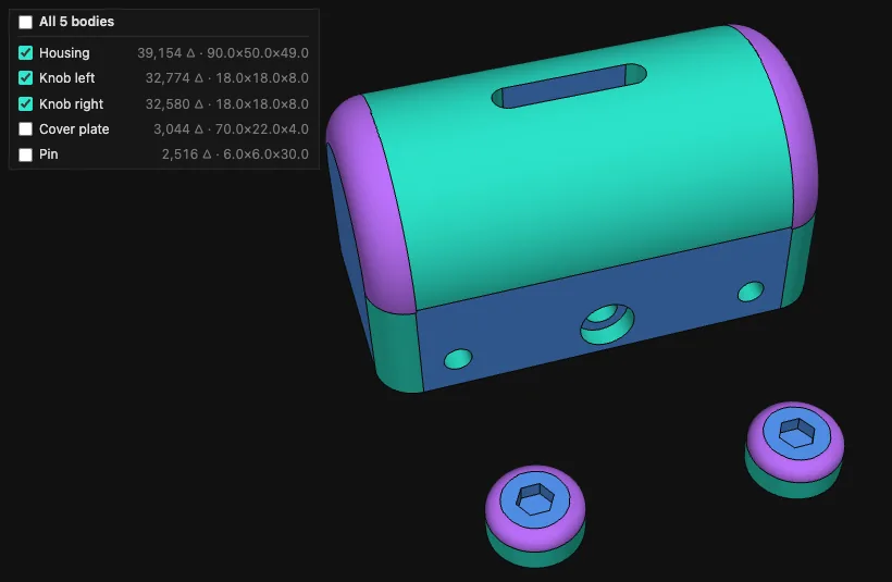
If a file holds several parts, Mesh2Solid lists every body with its triangle count and size. Tick only the ones you need – analysis and STEP export then cover just those. Hover a row and the body lights up in the model.
Right click to give each body a name; it goes into the STEP file as the body name and shows up again in your CAD.
How: body list under “File” – tick, right click → “Rename”.